In today’s fast-evolving manufacturing landscape, understanding the List of CNC Machine Codes is more than just a necessity—it’s a game changer. CNC (Computer Numerical Control) technology stands at the heart of modern manufacturing processes, transforming digital designs into physical parts with precision and speed. The intricacies of CNC programming, particularly the relevance of G-code and M-code, form the backbone for effectively operating this sophisticated machinery. Therefore, a comprehensive grasp on this List of CNC Machine Codes is indispensable for anyone looking to excel in the field of manufacturing and machining.
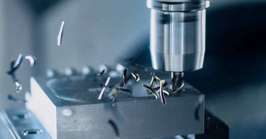
In this article, we will navigate through the complexities of CNC programming by offering a detailed G-Code and M-Code reference. Our exploration will include codes that are pivotal for operations such as G00 for Rapid Positioning, G01 for Linear Interpolation, through to specific functionalities like G17 for XY Plane Selection, and system selections with G20 and G21 for Inches and Millimeters, respectively. By the conclusion, our aim is to equip you with a thorough understanding of these essential codes, ensuring you’re well-prepared to maximize the efficiency and accuracy of your CNC machining operations.
G00: Rapid Positioning
In CNC machining, G00 is a critical code used for rapid positioning of the cutting tool. This command moves the tool to a specified point as quickly as possible, which is essential for reducing non-productive time during machining processes. However, it’s crucial to note that G00 should never be used to initiate a cutting action. Due to its high-speed nature, using G00 to enter a cut could result in damage to the cutter or even more severe machine damage.
Key Aspects of G00: Rapid Positioning
- High-Speed Movement: G00 allows the machine to move at its maximum possible speed to the desired coordinate, which can be specified using X, Y, Z, A, and B coordinates. This makes it an efficient way to position the tool near the start point of a cut without engaging the material.
- Modal Nature: The command is modal, meaning once set, it remains active until changed by another G-code. This is particularly useful for sequences where multiple rapid movements are required without altering the speed settings.
- Safety Considerations: When using G00, it’s advisable to ensure the path is clear of any obstructions such as clamps, fixtures, or the workpiece itself. Special care should be taken to avoid any collisions, which can be catastrophic due to the high speed of movement.
- Usage in Programming: Typically, G00 is used to position the tool before starting a cut or when changing tools. For example, a common sequence in programming might look like this: N10 G90 (Set Absolute mode); N20 G00 X1.0 Y1.0 (Position the machine at P1); N30 G00 X9.0 Y7.0 (Move directly to P2 in Rapid Traverse);. This sequence demonstrates how G00 is used to rapidly move the tool across different coordinates.
- Interpolation and Dog Leg Moves: On older machines or those with specific settings, G00 might not move in a straight line but rather move each axis sequentially, known as “dog legging”. This could be critical to consider in environments with potential obstructions.
- Practical Tips: Before executing a G00 command, it’s often wise to pull the Z-axis up to a safe distance to avoid any accidental engagement with the material or fixtures. Also, leaving room for lead-ins and lead-outs can prevent errors in rapid movements.
By understanding and applying G00 effectively, we can enhance the efficiency of CNC machining operations while ensuring safety and precision in tool positioning.
G01: Linear Interpolation
In CNC machining, the G01 code is essential for linear interpolation, where the tool moves from one point to another in a straight line at a specified feed rate. This process is fundamental for achieving precise cuts and is utilized across various CNC operations, from lathes to machining centers.
Key Aspects of G01: Linear Interpolation
- Controlled Movement: The G01 command allows for controlled linear motion, where the speed of the tool’s movement is dictated by the feed rate (F value). This is crucial for operations that require the tool to cut or extrude material in a straight line.
- Programming the Command: To implement G01, the end position is specified with X, Y, and Z values, along with the feed rate using the F value. This ensures the machine tool moves smoothly along the calculated path, maintaining the desired speed throughout the operation.
- Versatility in Application: G01 is not limited to simple tasks but is also integral in complex machining operations such as contouring, pocket milling, and other detailed linear cutting processes. It is commonly paired with G90 (absolute positioning) or G91 (incremental positioning) to define the movement type.
- Feed Rate Adjustments: During operation, if adjustments to the feed rate are needed—perhaps due to material resistance or tool wear—these can be made by altering the F value in subsequent command lines without reissuing the G01 command. This flexibility is vital for maintaining optimal cutting conditions and preventing tool damage.
- Error Handling: It’s important to ensure that at least one axis is specified in the G01 command to avoid programming errors. Additionally, settings like cutter radius compensation (G41 or G42) and absolute coordinate positioning (G53) can alter the tool path, so understanding their effects is crucial for accurate programming.
- Practical Uses and Safety: In practical scenarios, G01 is used extensively for creating straight cuts or extrusions. Operators must ensure that the programmed path is clear of obstructions and that the tool is correctly configured to handle the specified material and cutting conditions. Safety measures, such as verifying clearances and tool integrity before operation, are essential to prevent machine damage or accidents.
By mastering the G01 command, we can significantly enhance the precision and efficiency of CNC machining operations, making it a cornerstone of modern manufacturing technology.
G02: Circular Interpolation (Clockwise)
In CNC machining, the G02 code is pivotal for executing circular interpolation in a clockwise direction. This command enables the tool to move along a circular arc from its current position to a new coordinate, ensuring precise and smooth circular cuts. The command’s functionality is crucial for intricate machining operations that require arcs or rounded details.
Key Aspects of G02: Circular Interpolation (Clockwise)
- Circular Arc Movement: G02 directs the CNC machine to move in a circular arc, which can be defined in terms of radius or by specifying the center point of the arc relative to the starting position. This movement is essential for creating rounded features in the machined part.
- Syntax Variations: There are two primary ways to program G02:
- “R” Syntax: For example, G02 X12.5 Y14.7 R2.0 F0.2; where X, Y are the target coordinates, R is the radius of the arc, and F is the feed rate.
- “IJK” Syntax: For example, G02 X12.5 Y14.7 I1.0 J2.0 F0.2; where I, J are the coordinates of the arc’s center point relative to the starting position. This method provides a double check of the arc’s accuracy as the machine calculates the exact center and ensures it is equidistant from both endpoints.
- Controlled Feed Rate: The feed rate, or the speed at which the tool moves, is crucial for achieving the desired surface finish and accuracy. It must be carefully set to match the material properties and the specific cutting conditions.
- Mode and Coordinate System: The movement can be programmed in either absolute (G90) or incremental (G91) coordinate modes. The choice depends on the programming style and the requirements of the specific CNC operation.
- Examples of Usage:
- Example in Absolute Mode: N10 G90; N20 G01 X4.0 Y0.0 F0.1; N30 Y2.0; N40 G02 X10.0 Y10.0 R5.0 F0.5; Here, G02 is used to move the tool in a clockwise direction along a circular path with a radius of 5.0 units.
- Example in Incremental Mode: N10 G91; N20 G01 X4.0 F0.1; N30 Y2.0; N40 G02 X6.0 Y7.0 R5.0 F0.5; This sequence uses incremental coordinates to define the arc’s end point relative to its start point.
- Practical Considerations: When using G02, it’s important to ensure that there are no obstructions in the tool’s path and that the tool is capable of handling the specified arc without causing damage to the workpiece or the machine itself. Additionally, understanding the limitations of the “R” format is crucial, especially for arcs greater than 180 degrees, where the “IJK” format offers more reliability and precision.
By integrating G02 effectively into CNC programming, we can enhance the capability to produce complex geometrical shapes, thus expanding the range of possible machining projects. This command’s precise control over circular movements is indispensable for high-quality CNC machining.
G03: Circular Interpolation (Counterclockwise)
In CNC programming, G03 is used for counter-clockwise circular interpolation, allowing for precise and smooth circular cuts in the opposite direction compared to G02. This command is essential when working on projects that require arcs or curves that loop counter-clockwise, providing versatility in machining intricate designs.
Key Aspects of G03: Circular Interpolation (Counter-Clockwise)
- Counter-Clockwise Arc Movement: G03 enables the tool to create arcs moving in a counter-clockwise direction. This is crucial for forming specific geometric features on a workpiece that are not achievable with straightforward linear motion.
- Syntax and Parameters: The typical syntax for a G03 command might look like G03 X10 Y10 I3.0 J4.0 F0.5;, where X and Y are the endpoint coordinates, I and J are the center point coordinates relative to the starting point, and F is the feed rate. This syntax ensures that the tool moves smoothly along the calculated path.
- Using IJK or R Values: While the R value can be used for specifying the radius directly, using IJK values allows for double-checking the correctness of the arc. The CNC controller calculates the center’s coordinates via IJK, ensuring that it is equidistant from both endpoints. This method provides an additional layer of verification that is absent when using the R value alone, which does not allow for such a check and can lead to inaccuracies in arcs spanning more than 180 degrees.
- Practical Applications and Examples: For example, if we need to machine a part with a counter-clockwise arc starting from position X20 Y10 and ending at X50 Y40, the command might be set as N20 G03 X50 Y40 I0 J30 F0.5;. This would move the tool from the starting point to the endpoint while maintaining a smooth and precise arc, with the center calculated relative to the initial position.
- Considerations for Machine Setup: It’s essential to ensure that the machine is correctly set up for using G03, with clearances checked and the tool properly aligned. This preparation helps prevent potential collisions and ensures the machine can handle the specified path without any issues.
By incorporating G03 into CNC machining operations, we can expand our capabilities to include more complex and varied geometrical shapes, enhancing the overall versatility and precision of the machining process.
G04: Dwell
In CNC machining, G04, known as the Dwell command, plays a crucial role by pausing the machine’s operations for a specified period. This command is particularly useful not only during cutting operations to enhance precision but also for various non-cutting functions within the machining process.
Key Aspects of G04: Dwell
- Purpose and Functionality: G04 allows the machine to stop or dwell, which is instrumental during operations that require a temporary halt. For instance, in lathe operations, it’s primarily used to break chips during drilling, counterboring, grooving, or parting-off. The dwell helps in managing the debris from cutting, thus preventing any potential machine jams or part defects.
- Applications in Milling and Turning: On milling machines, the G04 command is often employed to ensure the machine accurately follows a path, especially after long straight runs that end with a corner. This use is vital on older machines to compensate for any lag in response. In turning, it can be used to eliminate tool marks left by the end thrust of the cutting tool.
- Syntax and Programming: The command for a dwell is typically written as G04, followed by a parameter that specifies the duration of the pause. This could be in milliseconds (e.g., G04 P500 for a 500-millisecond pause) or in terms of spindle revolutions (useful for applications like chip breaking). It’s advisable to place the dwell command on its own line for clarity, especially if your machine uses alternative dwell words like “X” or “U.”
- Considerations for Effective Use: While dwells are useful, they represent unproductive time where the machine is not actively machining. Therefore, it’s important to minimize dwell time and explore alternative methods to achieve the desired outcomes without pausing the machine. Additionally, some CNC controls, like those from Fanuc, allow the use of G04 without a specific duration, enabling the machine to pause until it has caught up with all commands.
Practical Tips for Implementing G04
- Optimize Dwell Times: Always aim to keep dwell times as short as feasible. Extended dwells can lead to inefficiencies in the machining process.
- Clear Programming: If your machine uses different codes for dwell (like “X” or “U”), ensure these are clearly mentioned in the program to avoid confusion.
- Avoid Unnecessary Use: If your machine is capable of following paths accurately without the need for dwells, avoid using them as they can leave marks on the finished part.
By integrating the G04 command wisely into your CNC programming, you can enhance the machine’s operational efficiency and precision, while also managing specific machining challenges effectively.
G17: XY Plane Selection
In CNC programming, G17 is the code used to select the XY plane for operations that involve circular interpolation, such as G02 and G03, which are used for machining arcs and circles. The selection of the XY plane implies that the arcs or circles will be processed parallel to the XY plane, revolving around the Z-axis. This is the standard plane used when machining profiles that lie flat on the machine table, making it a fundamental aspect of CNC machining for a wide array of manufacturing tasks.
Modal Nature of Plane Selection
The selection of a plane using G17 is modal, which means once it’s set, it remains active until a different plane selection code is invoked. This feature is particularly useful for streamlining the programming process, as it eliminates the need to repeatedly specify the plane for each operation within the same context.
Impact on Other Commands
The choice of the working plane influences several other commands in CNC programming:
- G02/G03 (Circular Interpolation): These commands, which are used for creating arcs, depend on the selected plane to define the arc’s orientation in 3D space.
- G41/G42 (Cutter Radius Compensation): The compensation for the cutter’s radius is calculated relative to the selected plane, which is critical for achieving the desired precision in the final machined product.
- G43/G44 (Cutter Length Compensation): These commands adjust the tool length, which is crucial for maintaining the correct depth of cut, and the compensation is applied along the axis perpendicular to the selected plane.
Programming Considerations
It is advisable to specify the plane selection at the beginning of a program to set a clear operational context. This is typically done in the preamble or safety block of the G-code program. Most G-code programs default to the G17 mode, and while G18 (XZ plane) and G19 (YZ plane) are also available, they are less commonly used compared to G17.
Practical Usage
When programming, especially with G-code that involves transitions between different tools or operations, we always ensure to reset to G17 after each tool change or section of the program. This practice helps in maintaining consistency and safety throughout the machining process. It prevents any confusion that might arise if the machine were to default to another plane unexpectedly due to program interruptions or modifications.
By understanding and effectively using G17, we can enhance the precision and efficiency of our CNC machining operations, ensuring that each component we produce meets rigorous standards of accuracy and quality. The strategic use of this command allows us to handle complex machining tasks with confidence, knowing that our setup is optimized for the best possible outcomes.
G20: Inch System Selection
In the realm of CNC machining, the G20 code plays a crucial role by setting the system to interpret all coordinate values in inches. It’s vital to understand that G20, along with its counterpart G21, does not convert the measurements of your part program from one unit system to another. Rather, these codes specify to the CNC controller the unit of measurement in which the coordinates of your G-code program are expressed.
Understanding the Function of G20
G20 is used to inform the CNC machine controller that all subsequent coordinates in the G-code program are provided in inches. This is particularly important for ensuring that the machine operates under the correct unit system for the intended design dimensions. It’s a common practice to set this code at the beginning of a program to establish a clear and consistent framework for unit interpretation throughout the machining process.
Best Practices for Implementing G20
- Early Programming: We always program G20 near the start of the CNC program, before any motion commands are executed. This practice prevents any confusion about the units being used, especially in complex programs that involve multiple tool changes and operations.
- Avoid Mixing Units: Mixing G20 and G21 (which sets the system to metric units) within the same program can lead to confusion and errors. To maintain clarity and precision in our machining operations, we ensure that only one unit system is used throughout a single program.
- Consistency After Tool Changes: Although it’s typically only necessary to specify the unit system once, we find it beneficial to reiterate the G20 command after each tool change when running complex programs. This step adds an extra layer of safety, ensuring the machine consistently interprets all coordinates in inches, regardless of the program’s position when started.
Technical Considerations and Limitations
- Internal Conversion: Once G20 is set, the CNC controller uses this information to convert all coordinate data into the internal unit system it operates on, which can be either metric or imperial. This conversion is crucial for the accurate execution of the G-code program.
- Precision and Increments: The usual minimum increment in G20 programming is one ten-thousandth of an inch (0.0001 inches). This precision level is suitable for most applications but is distinctly coarser compared to the metric system’s minimum increment under G21, which is one micrometer (0.001 mm).
By effectively utilizing the G20 code in our CNC programming, we can ensure that all measurements are accurately interpreted and processed in inches, aligning with the design specifications and enhancing the overall precision of our manufacturing processes.
G21: Millimeter System Selection
In the realm of CNC machining, setting the correct unit of measurement for programming is crucial for accuracy and precision. The G21 G-code is essential for specifying that all subsequent coordinates in a CNC program should be interpreted in millimeters. This setting is particularly important in contexts where precise metric measurements are required for the design and manufacturing processes.
Understanding G21: Millimeter System Selection
G21 is used to inform the CNC machine controller that all positional data, offsets, rates, and other relevant parameters are to be read and interpreted in millimeters. It’s a common practice to set this code at the beginning of the program to ensure a clear and consistent understanding of the measurement units throughout the machining process.
Best Practices for Implementing G21
- Early Implementation: We always ensure to program G21 at the start of the CNC program, before any motion commands are initiated. This approach prevents any potential confusion about the units being used, especially in complex programs that involve multiple operations and tool changes.
- Consistency Across the Program: To avoid errors and maintain precision, it’s crucial not to switch between G20 (which sets the system to inches) and G21 within the same program. Consistency in unit usage ensures that all numerical values are interpreted correctly by the CNC controller.
- Reiteration Post Tool Changes: Although typically it’s only necessary to specify the unit system once at the start, reiterating the G21 command after each tool change can serve as an added precaution, particularly in lengthy or complex machining operations. This practice helps in reinforcing the metric measurement system, ensuring that the machine does not default to another unit unexpectedly.
Technical Considerations and Limitations
- Internal Conversion: Once G21 is activated, the CNC controller utilizes this setting to convert all coordinate data to the internal unit system it operates on. This conversion is vital for the precise execution of the G-code program.
- Precision and Increments: The minimum increment in G21 programming is typically one micrometer (0.001 mm), which offers a higher resolution compared to the imperial system used under G20. This finer increment is advantageous for detailed and precise machining tasks.
By effectively utilizing G21 in our CNC programs, we ensure that all dimensions are accurately processed in millimeters, aligning perfectly with the metric-based design specifications. This precision is fundamental to achieving the high-quality standards required in modern manufacturing environments.
Throughout the exploration of CNC machine codes, we’ve delved into the intricacies of G-code and M-code, highlighting their indispensable role in modern machining processes. By dissecting codes from G00 for Rapid Positioning to G21 for Millimeter System Selection, we’ve seen how each code serves a specific function, contributing to the efficiency, precision, and versatility of CNC operations. Our journey through these codes underscores their significance in not only executing operations with meticulous accuracy but also in optimizing machining workflows, ultimately enhancing the quality of the manufactured parts.
Understanding and applying these codes correctly is fundamental for anyone involved in CNC machining, whether for improving existing operations or embarking on new manufacturing projects. The broader implications of mastering these codes extend far beyond their immediate operational benefits, significantly impacting the field of manufacturing by facilitating the production of components with unparalleled precision and speed. As we continue to push the boundaries of what’s possible in manufacturing, the knowledge of CNC machine codes will remain a critical tool in the arsenal of engineers, machinists, and manufacturers worldwide, shaping the future of innovation.
FAQs
1. What are the purposes of G-codes and M-codes in CNC machining? G-codes and M-codes are essential for CNC machining operations. G-codes (Geometric Codes) direct the machine on movements and paths, such as:
- G00: Rapid Positioning
- G01: Linear Interpolation
- G02: Circular Interpolation Clockwise
- G03: Circular Interpolation Counterclockwise
M-codes control miscellaneous functions:
- M00: Program Stop
- M02: End of Program
2. Can you explain what G-code is used for in CNC machines? G-code is a programming language used by CNC machines to execute specific tasks. It stands for “Geometric Code” and guides the machine on where to move, the speed of movement, and the path to follow. This code is fundamental in shaping and creating precision parts and components.
3. What are the common G-codes and M-codes used in manual part programming for Fanuc control systems? For manual programming of Fanuc control systems, several common G-codes are used:
- G00: Rapid traverse
- G01: Linear interpolation with feed rate
- G02: Circular interpolation (clockwise)
- G03: Circular interpolation (counterclockwise)
- G2/G3: Helical interpolation
- G04: Dwell time in milliseconds
- G05: Spline definition
- G06: Spline interpolation
4. What does the G56 G-code represent in CNC programming? In CNC programming, G56 is one of several G-codes used for setting work offsets, which help ensure the workpiece is positioned correctly at its true zero position. The related commands include:
- G54: Work Offset 1
- G55: Work Offset 2
- G56: Work Offset 3



Leave a Comment