
In the realm of manufacturing and machining, understanding the intricate workings of lathe parts is crucial for anyone looking to master CNC (Computer Numerical Control) technology. These components are the heartbeat of the lathe machine, enabling it to perform a vast array of tasks with precision and efficiency. The significance of these parts extends beyond mere functionality; they are the building blocks that ensure the machine’s operational integrity and the quality of the work it produces. As we delve into the complexities of CNC lathe machine parts, it’s essential to grasp the role and importance of each component in the machine’s overall performance.
Our exploration will cover the essential elements that comprise a CNC lathe machine, starting with the headstock, an integral part that houses the machine’s spindle. We will also examine the lathe bed, the foundation upon which all other parts are mounted, and the chuck, which holds the workpiece in place. Other critical components like the tailstock, tailstock quill, and foot switch or foot pedals will be discussed to provide a comprehensive understanding of their functions. Additionally, the CNC control panel, the brain behind the machine’s operations, will be highlighted. By the conclusion of this article, we aim to provide a thorough insight into the various lathe parts and how they contribute to the effectiveness and versatility of the CNC lathe machine.
What is a CNC Lathe Machine?
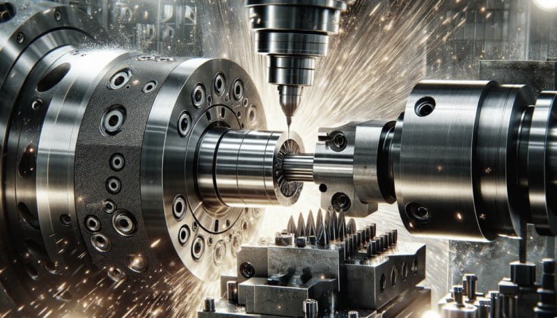
A CNC lathe, also known as a CNC turning machine, is a highly sophisticated piece of equipment that utilizes Computer Numerical Control (CNC) to automate the process of machining. This technology allows for the precise control of the machine tools, enabling the lathe Parts to perform a variety of functions such as cutting, sanding, drilling, and turning with exceptional accuracy.
The core of a CNC lathe is its ability to rotate a workpiece against a fixed cutting tool. The operations of the machine are governed by coded instructions that are input into the machine’s computer system. These instructions dictate the movement of the components along various axes, which is essential for the machining of complex shapes and designs. The CNC system can handle tasks across multiple axes simultaneously, which significantly enhances efficiency by eliminating the need to reposition the workpiece manually.
One of the critical components of a CNC lathe is the main spindle, which includes the spindle assembly and the spindle drive system. This part of the machine is responsible for the rotation of the chuck and the workpiece. Attached to the main spindle, the chuck is a key element that holds the materials being machined. It can accommodate various sizes of materials, thanks to its adjustable jaws or the use of collets for smaller diameter parts.
The headstock houses the main motor and plays a pivotal role in driving the main spindle. Positioned at the front of the CNC turning machine, the headstock ensures that the spindle operates at the desired speed and with the necessary power. On the opposite end, the tailstock provides support for longer workpieces, enhancing stability during the machining process. It is typically attached directly to the bed of the machine and can be adjusted using hydraulic force to suit different lengths of materials.
The bed of the CNC lathe serves as the foundation upon which all other components are mounted. It supports the carriage, which facilitates the movement of the cutting tools. The carriage moves along the bed, guided by the guide way, which ensures smooth and precise lateral and vertical movements. This arrangement allows the cutting tool to interact with the rotating workpiece to perform the desired machining operations.
In summary, the CNC lathe combines traditional lathe Parts design with modern technology to create a highly efficient and precise machining tool. Its versatility in handling various materials and complex part designs makes it an indispensable tool in modern manufacturing environments.
Headstock
Components of the Headstock
The headstock of a CNC lathe is a critical assembly that houses several key components essential for the machine’s operation. Central to the headstock is the main spindle, the primary rotating element that drives the workpiece. The spindle is robust, typically made from high-grade steel or cast iron, designed to withstand the stresses and loads of machining. Attached to the spindle, you’ll find the spindle nose, which serves as the attachment point for various workholding fixtures such as chucks and collets.
Workholding devices like chucks and collets are crucial for securing the workpiece. Chucks come in different types, such as three-jaw or four-jaw, and use adjustable jaws to hold the workpiece securely during operations. Collets offer an alternative method, providing high precision by clamping around the workpiece. The drawbar, another vital component, secures these devices to the spindle.
Power transmission within the headstock is facilitated by either belt or gear drive systems, or in some advanced models, direct drive systems. Belt drives, which use a tensioned belt to connect the motor to the spindle, are common in lower-speed applications. Gear drives, consisting of interlocking gears, are suited for high-speed operations due to their ability to handle higher torques. Direct drive systems offer enhanced accuracy by eliminating the intermediary components, directly connecting the spindle to the motor.
Function and Importance
The headstock’s primary role is to transmit power from the motor to the spindle, enabling the necessary rotational motion for machining tasks such as turning, drilling, and threading. This is accomplished through a combination of the motor, spindle, and either a belt, gear, or direct drive system, depending on the specific requirements of the operation.
Moreover, the headstock is pivotal in maintaining the stability and accuracy of the machining process. It does so by ensuring that the workpiece is securely held and centered, minimizing potential vibrations or deflections that could impact the machining quality. The robust construction and precise alignment of the headstock components are crucial in this regard.
Regular maintenance and care of the headstock, especially the spindle and its bearings, are essential for prolonged accuracy and performance. This includes routine lubrication and inspection to prevent issues such as deflection, vibration, and runout, which could adversely affect the machine’s precision.
In summary, the headstock is not just the power behind the CNC lathe Parts but also a cornerstone of its operational integrity, playing a key role in both the performance and longevity of the machine.
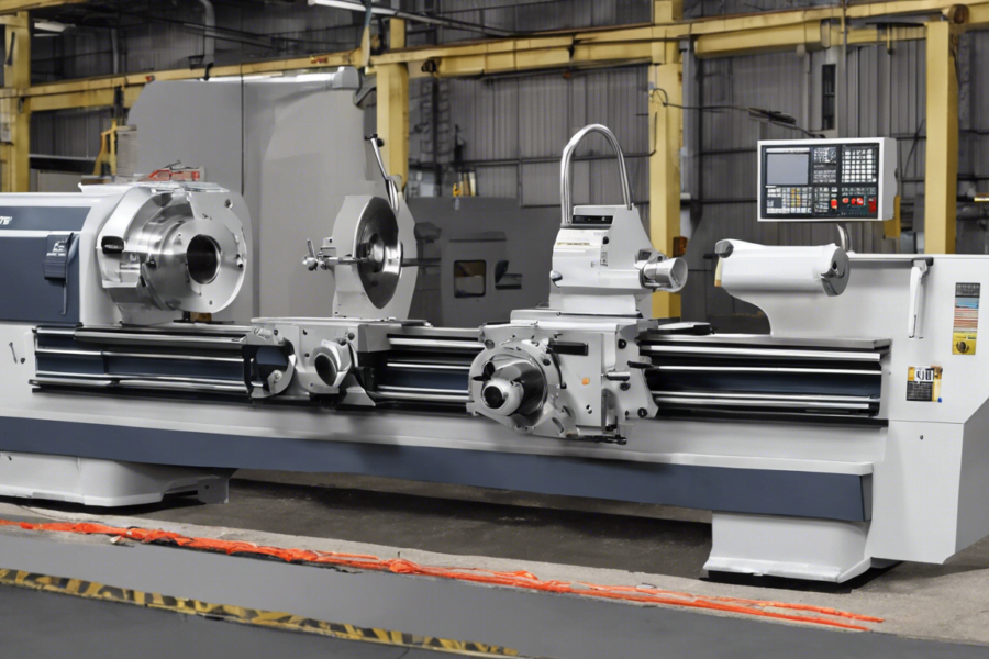
CNC Lathe Bed
The bed of a CNC lathe serves as the chassis, anchoring all key components and providing the structural integrity necessary for precise machining. As the primary foundation, it supports functional subassemblies and dictates the overall stability and performance of the lathe.
Materials Used
We use a variety of materials to construct the bed of a CNC lathe, each selected for its specific properties to enhance the machine’s functionality and durability. Common materials include cast iron, mild steel, and ductile cast iron, as well as innovative substances like Granitan, an artificial stone substitute. Cast iron, particularly grey cast iron, is favored for its excellent damping capacity, which is crucial for absorbing vibrations during machining. This property stems from the graphite flakes within its structure, which help to dissipate vibrational energy effectively.
In some advanced designs, we also incorporate materials like steel or artificial granite. Steel provides additional strength and rigidity, although it is less common due to its potential to vibrate under heavy loads. Artificial granite, on the other hand, offers exceptional toughness and minimal risk of cracking or chipping, alongside superior vibration damping capabilities.
Function and Importance Lathe Parts
The primary function of the CNC lathe bed is to maintain the alignment and accuracy of the machine’s components over prolonged periods. It houses the guide rails and headstocks, and supports critical elements like the carriage and tailstock. The bed’s design, particularly the bedways, is integral to the machine’s functionality. These precision-ground surfaces, which can be configured as box ways, v-ways, or dovetail ways, provide a smooth path for the carriage and tailstock, facilitating precise movements.
Thermal stability is another critical aspect, especially in high-precision machining environments. The materials and design of the bed must minimize thermal deformation to maintain machining accuracy. This is achieved through the use of materials like grey cast iron and designs that enhance the bed’s stiffness and torsional rigidity. For instance, the arrangement of ribs within the bed’s structure is strategically planned to improve static stiffness and reduce bending and torsion.
In summary, the CNC lathe bed is not just a physical foundation but a pivotal element that directly impacts the precision, efficiency, and longevity of the CNC lathe. Its design and the materials used are carefully chosen to meet the stringent requirements of modern machining operations, ensuring that each component functions seamlessly within the broader system.
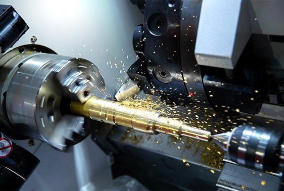
Chuck
A lathe chuck is mounted on the headstock of a lathe Parts and can be actuated manually or under power, primarily used to hold a rotating workpiece. This key component is crucial for the lathe’s functionality, as it directly interacts with the workpiece during machining processes.
Types of Chucks Lathe Parts
Chucks vary significantly in design and function, catering to different machining needs:
- Manual Lathe Chuck: Operated manually using a T-handle wrench to open or close the jaws, which may be one-piece or two-piece with a removable top jaw.
- Power Lathe with Quick-Change Jaws: Enhances productivity by minimizing setup time, ideal for manufacturers prioritizing quick job changes.
- Power Lathe Chucks with Through Hole: Suitable for large raw material diameters, these chucks offer high run-out and repeat accuracy, essential for bar-feeding applications.
- Power Lathe Chucks without Through Holes: Similar to those with through holes but are better protected against dirt and chips, making them suitable for both vertical and horizontal lathes.
- Pneumatic Power Chucks: Featuring large through-bores, these are optimal for machining pipes and similar workpieces, commonly used in the Oil and Gas industries. They operate pneumatically, which eliminates the need for a hydraulic unit.
Other notable types include:
- Three-jaw universal chucks and four-jaw independent chucks for general purposes.
- Collet chucks and magnetic chucks, which are specialized for precise applications.
- Vacuum Chucks and Screw Chucks designed for specific holding conditions.
Function and Importance
Chucks serve as the primary point of contact between the machine and the workpiece, ensuring stability and accuracy during machining. The selection of the appropriate chuck impacts the efficiency and capability of a CNC lathe machine, influenced by factors such as workpiece specifications, machining requirements, and operator expertise.
The importance of chuck size is also notable:
- Secure Workholding: Larger chucks can handle bigger workpieces, enhancing the machine’s versatility and safety.
- Stability and Accuracy: Larger chucks provide more contact area, reducing vibrations and improving precision.
- Maximizing Machining Capacity: Adequate chuck size allows for fewer repositionings, increasing operational efficiency.
Maintaining lathe Parts chucks is crucial for operational accuracy and longevity. Effective practices include regular cleaning, lubrication, wear and tear inspection, alignment checks, and professional servicing. These maintenance actions ensure that the chuck continues to perform optimally, supporting the overall productivity and precision of the CNC lathe machine.
Tailstock
Located opposite the headstock on a CNC machine lathe, tailstocks are instrumental in securing and supporting the free end of a workpiece while it is being machined. The tailstock ensures that the workpiece’s longitudinal rotary axis is held steady and fixed precisely parallel to the lathe bed. Its position is adjustable along the bed ways to accommodate pieces of varying lengths. Once locked in place, the tool is mounted and moved into the exact position using a leadscrew.
Function and Importance
The primary function of the tailstock is to provide stability and support to the workpiece during machining operations. This is particularly crucial when working with long, slender pieces or when precision is paramount. The tailstock’s rigidity and its ability to securely hold a workpiece on center significantly affect the quality of the finished piece. Proper alignment with the headstock is essential to avoid problems such as tapering and chatter—marks in the workpiece due to the part not being held tight enough by the tailstock. Regular maintenance and correct alignment ensure that tapering, inaccuracies, and other distortions are minimized, thereby enhancing the overall machining quality.
Use Cases
Tailstocks are not required for every machining job but are crucial for certain applications:
- Supporting Long, Slender Pieces: When machining pieces with a high length-to-diameter (LTD) ratio, the risks of flaws in the finished piece increase. Tailstocks are necessary for pieces that exceed a 3:1 LTD ratio to ensure stability and quality.
- Drilling Operations: Tailstocks are also used to drill out the centers of workpieces. A cutting tool, like a drill, tapper, or reamer, contained within the tailstock is used to create holes of precise depth, shape, and diameter. Unlike with a drill press or milling machine, the tool within the tailstock remains stationary while the workpiece is rotated.
- Handling Heavy or Large Workpieces: For heavy or large workpieces that could easily become dislodged from the workholding device during heavy machining, the tailstock provides increased stability.
- Machining Multiple Diameters: When a component requires multiple diameters with a high degree of concentricity accuracy, a tailstock allows all the diameters to be machined in a single operation, enhancing both efficiency and precision.
In summary, the tailstock is a versatile and essential component of a CNC lathe, crucial for maintaining the stability, accuracy, and quality of various machining operations. Its correct use and maintenance are key to leveraging the full capabilities of the CNC machine.
Tailstock Quill Lathe Parts
The quill in a tailstock is a cylindrical component that plays a crucial role in the operation of a CNC lathe Parts. Made typically of steel, the quill is precision-machined to ensure smooth and accurate in-and-out movement within the tailstock body. This movement is crucial as it adjusts the distance between the tailstock and the headstock, accommodating workpieces of various lengths.
Function and Importance
Operated either by a handwheel or lever, the quill allows for fine adjustments to be made to its position, which is essential for precision machining. In some advanced CNC lathes, the quill movement is automated, providing even more precise and repeatable adjustments. This feature is particularly important when the workpiece requires drilling or turning between centers.
The quill’s primary function is to support the workpiece during these operations, holding it firmly to maintain its position. This support is vital for achieving high-quality and accurate parts. Moreover, the proper lubrication and maintenance of the quill are imperative to ensure its continuous smooth operation and to extend its service life. Regular care prevents issues that could compromise the machining process, such as misalignment or excessive wear, which could lead to inaccuracies in the final product.
By maintaining the quill’s alignment and ensuring it operates smoothly, we can significantly enhance the overall effectiveness and efficiency of the CNC lathe machine. This not only improves the quality of the output but also reduces potential downtime caused by mechanical failures or the need for adjustments during the machining process.
Foot Switch or Foot Pedals
Foot switches, also known as foot pedals or stomp switches, are vital components in various industrial and medical applications, allowing operators to control machinery hands-free. These devices are especially useful in environments where manual operation poses a safety risk or where the operator’s hands are occupied with other tasks.
Control Functions
Foot switches perform essential control functions in machinery by making or breaking an electrical circuit. They operate under a simple principle: when the pedal is pressed by the foot, the switch activates, connecting the circuit and enabling the machine to function. Releasing the pedal breaks the circuit, turning the machine off. This mechanism is similar to traditional electric switches, involving normally open (NO) and normally closed (NC) contact points.
Different types of foot switches include mechanical and inductive models. Mechanical foot switches, often using a rack and pinion drive, are traditional and straightforward in their operation. Inductive foot switches, on the other hand, operate based on electromagnetic induction, offering a more sophisticated control mechanism.
For enhanced functionality, foot pedal potentiometers are used in conjunction with variable speed motors. These devices allow the operator to adjust the speed of the motor by varying the pressure applied to the pedal. This is particularly beneficial in applications requiring precise speed adjustments, such as sewing machines, shearing machines, and other specialized equipment.
Safety Features
Safety is a paramount concern when using foot switches, especially in industrial settings. These devices are designed to increase operational security by allowing the operator to maintain a safe distance from hazardous areas. For instance, footswitch bellows, also known as air actuators, enable electrical circuit control securely from a distance. They work by transferring air pressure through tubing to activate the switch, making them ideal for environments with explosive gases or other hazardous materials.
Press brake foot switches are specifically designed to enhance safety in press brakes used in metal fabrication. They allow operators to keep their hands free and can be used as primary or supplementary activation controls. Some models feature a two-press operation technique, which increases safety by allowing time for adjustments before the machine fully engages.
To prevent accidental operation, many foot switches are equipped with safety covers and anti-slip pads. These features ensure the switch does not move or activate unintentionally. Additionally, foot switches should be constructed from durable materials like flame-retardant plastics or metals to withstand mechanical and electrical stresses. Regular maintenance and inspection are crucial to ensure these components function safely and effectively.
In summary, foot switches are essential for enhancing both the functionality and safety of various machines. By allowing hands-free operation and providing necessary control adjustments, these devices play a crucial role in modern industrial and medical applications.
CNC Control Panel
Components and Interface
The CNC control panel, often regarded as the brain of the CNC machine, is pivotal in managing the operations and functionality of the entire system. This panel includes a variety of components such as function keys, switches, and a display screen that are essential for the daily operations of a CNC machine. The typical layout comprises:
- Power on/off key: This key is used to initiate or halt the machine’s operations.
- Display screen: Acts as the interface showing essential parameters and machine status.
- Edit button: Allows for the modification and editing of program codes directly from the panel.
- Jog keys: Facilitate the manual movement of multiple axes.
- MDI (Manual Data Input): Enables the operator to input commands one at a time directly into the system.
- MPG (Manual Pulse Generator): Provides manual control over the movement of the machine axes.
- MEM (Memory mode): Operates the machine using pre-programmed codes.
- Cycle Start / Feed Hold: These controls start or pause the machine operation.
- Coolant control: Manages the flow and operation of the cooling system.
- Letter & number keys: For inputting data or commands.
- Emergency stop: Immediately halts all machine activities and power supply.
- Rotary Switches: Each switch adjusts different settings such as feed rate, spindle speed, or operational mode.
Internally, the control panel houses critical components such as circuit and relay protection systems, a breakout board, an IO Board for signal transmission, and a USB to PC port for computer connectivity. Other connections include sockets for manual pulse generators, servo drivers, encoders, and emergency stops. The panel also integrates a PLC (Programmable Logic Controller) and DNC (Direct Numerical Control) for enhanced command execution and machine control.
Programming and Operation Lathe Parts
Operating a CNC machine involves various control panel functions that are crucial for precise and effective machining. Operators must be proficient in using the panel to execute a range of tasks:
- Programming Codes: Inputting and editing G-code to dictate machine actions.
- Handling Modes: Switching between different operational modes such as handle, jog, or MDI for incremental or continuous movement.
- Single Block and Optional Stop: These functions are used to trial run programs ensuring accuracy before full operations commence.
- Cycle Start: Activates the programmed machining operations.
- Overrides: During the operation, speed and feed can be adjusted using override functions to optimize machining conditions.
The control panel’s design may vary based on the type of CNC machine it operates with, such as lathes, mills, or grinders, each tailored to meet specific industrial needs. Its placement on an extendable arm allows operators to position the screen conveniently, enhancing usability and accessibility. The display unit is crucial as it provides real-time feedback about the machine’s status and the machining process, showing essential data or even detailed graphics depending on the complexity of the display.
Understanding and effectively managing the CNC control panel is fundamental for operators to ensure that the CNC machine performs optimally, adhering to precise specifications and achieving high-quality outputs. Regular training and familiarity with the control panel’s functions are essential for operators to harness the full potential of CNC technology.
Through this comprehensive exploration, we’ve delved into the pivotal components that form the essence of a CNC lathe machine, shedding light on their roles, significance, and how they synergize to enhance the machine’s performance and reliability. By understanding the intricacies of parts like the headstock, chuck, tailstock, and the bed, we glean insights into the meticulous design and operational dynamics that make CNC lathes indispensable tools in modern manufacturing. This underscores not only the technological marvel that CNC machines represent but also the critical importance of each component in achieving precision in machining tasks.
Drawing from the discussed elements, it’s evident that the proper functioning of a CNC lathe pivots on the harmonious interaction of its parts, along with the sophisticated control offered by the CNC control panel. The implications of this cohesiveness extend beyond the workshop floor, influencing innovation, efficiency, and quality in manufacturing processes. As technology advances, the role of CNC machines in shaping the future of manufacturing remains undeniably significant, inviting continued learning and adaptation. Moreover, the call for further research and development in this field promises to unveil even greater efficiencies, reinforcing the CNC lathe machine’s status as a cornerstone of modern industrial operations.
FAQs
What are the primary components of a CNC lathe machine? The CNC lathe machine consists of several key components including the headstock, collet and chuck, tailstock, lathe bed, and carriage. Each part plays a crucial role in the machine’s operation.
Can you list 10 parts of a lathe machine? Certainly! Here are 10 parts of a lathe machine:
- Control rod
- Tailstock spindle
- Feed-setting chart
- Tailstock handwheel
- Headstock spindle
- Ways (the linear rails of the lathe)
- Base
- Dead center
What are the fundamental elements of a lathe machine? A lathe machine is fundamentally composed of four main parts: the bed, spindle, turret, and tailstock. The spindle is particularly important as it holds and rotates the material being worked on.
What are the six major elements of a CNC machine? A CNC machine is comprised of six main parts:
- Input Devices – These are used to input instructions into the machine.
- Machine Control Unit (MCU) – Often considered the brain of the machine, it processes all input data.
- Machine Tool – This is the component that actually carries out the work.
- Driving System – This powers the movements of the machine.
- Feedback System – It ensures the machine operates accurately by monitoring and adjusting the machine’s operations.
Leave a Comment